⚡ Key Facts
- The 80% Rule: The National Electrical Code (NEC) mandates that continuous electrical loads must not exceed 80% of a circuit's or generator's maximum rated capacity to prevent thermal degradation and mechanical failure.
- Voltage Drop Thresholds: Supplying sensitive appliances with a voltage drop greater than 3% to 5% causes electric motors to draw excessive amperage, leading to overheating, shortened lifespans, and catastrophic compressor failure.
- Cord Length Limits: Running a standard 14 AWG cord beyond 50 feet under a 15-amp load can drop supply voltage below 110V on a nominal 120V circuit, creating an acute electrical fire hazard.
- Critical Separation: The Centers for Disease Control and Prevention (CDC) and the Consumer Product Safety Commission (CPSC) mandate operating generators at least 20 feet away from any structure, making long-distance, heavy-gauge distribution lines non-negotiable.
- Cord Jacket Ratings: Only heavy-duty cables marked with "W" ratings (such as SJTW or SOOW) are rated by Underwriters Laboratories (UL) to resist moisture, ultraviolet light, and oil exposure during severe winter storms and prolonged grid-down events.
When the grid collapses during a severe weather anomaly, your emergency power system is only as reliable as its weakest physical link. According to the U.S. Energy Information Administration (EIA), major weather disturbances have caused multi-day power interruptions to double in frequency over the past decade. In an extended grid-down scenario, bringing a portable generator to life is only half the battle. If you route power through undersized cords or run arbitrary wire lengths without calculating resistive line loss, you risk destroying the very equipment keeping your family safe—or worse, sparking an electrical structure fire. Safe, efficient off-grid power distribution requires methodical, technical discipline: calculating true load profiles, accounting for inrush surge capacity, selecting the exact American Wire Gauge (AWG), and strictly managing distance-induced voltage drop. For the practical checklist side, use the community emergency preparedness guide.
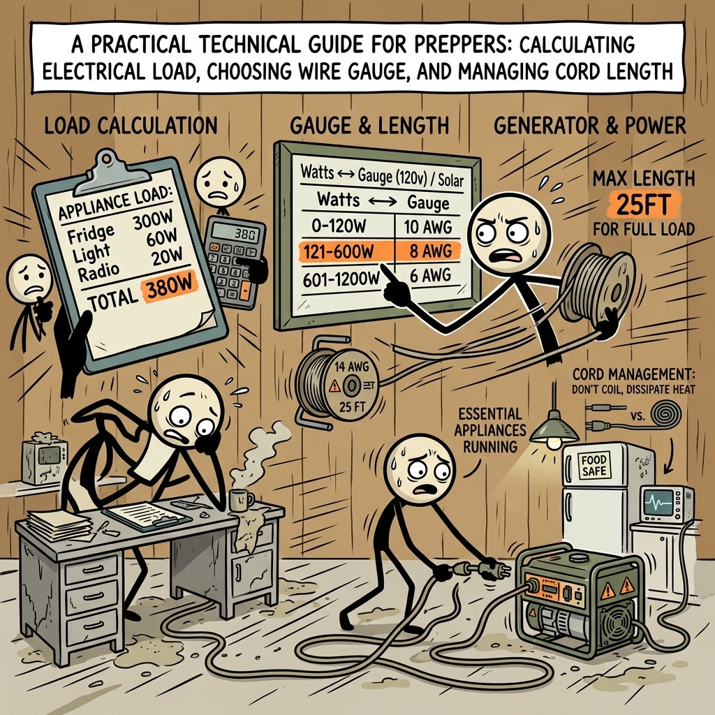
The Fundamentals of Load Math: Watts, Volts, and Amps
A reliable generator deployment starts with the fundamental relationship governing all direct and alternating current circuits: Ohm’s Law and Watt’s Law. Electricity in an emergency circuit is defined by three interrelated variables: Volts (electrical potential), Amperes or Amps (electrical current volume), and Watts (total electrical power). To manage electrical loads safely, you must convert these metrics fluidly using the standard power formula: For the practical checklist side, use the neighborhood preparedness network.
$\text{Watts} = \text{Volts} \times \text{Amps}$
$\text{Amps} = \frac{\text{Watts}}{\text{Volts}}$
In standard North American residential applications, portable generators output power at two nominal voltages: 120 volts (single-phase) for standard utility appliances, and 240 volts (split-phase) for high-draw systems like deep-well submersible pumps, electric water heaters, and split-system HVAC units. If you are drawing 1,800 watts from a standard 120V receptacle, your distribution line must carry 15 amps of current ($1,800 \div 120 = 15$). If you run that same 1,800-watt load at 240V, the current draw drops to 7.5 amps ($1,800 \div 240 = 7.5$), instantly cutting your conductor resistance and thermal losses in half. For the practical checklist side, use the emergency communication plan.
This mathematical distinction is why high-draw appliances operate at 240V. For preppers relying on smaller, portable units (2,000 to 4,500 watts), nearly all critical distribution occurs across individual 120V circuits. Underestimating the amperage carried across these 120V branch lines is the primary reason extension cords overheat, melt their PVC insulation, and trigger breaker trips under emergency conditions. For the practical checklist side, use the family emergency planning guide.
Resistive vs. Inductive Loads
When performing emergency generator load planning, you must categorize every piece of equipment into one of two load types: resistive or inductive. Failing to distinguish between these two will catastrophically overload your generator or blow output inverter modules the moment an appliance cycles on.
- Resistive Loads: These devices convert electrical current directly into heat or light using simple conductors. Examples include incandescent light bulbs, space heaters, electric frying pans, toasters, and basic coffee makers. Resistive loads have a constant power demand; an 800-watt electric skillet requires 800 watts to start and precisely 800 watts to maintain operation.
- Inductive Loads: These devices rely on electric motors, magnetic fields, and compressors. Examples include refrigerators, chest freezers, well pumps, sump pumps, furnace blower motors, and power tools. Inductive loads demand a massive surge of instantaneous current—known as locked-rotor amperage (LRA) or inrush current—to overcome mechanical inertia and magnetize the motor windings.
Inrush current typically demands two to four times the motor’s continuous operating wattage for an interval lasting between 500 milliseconds and three full seconds. If a modern high-efficiency chest freezer draws 200 running watts, its internal compressor motor can easily demand 800 to 1,200 starting watts when the thermostat engages. Your generation and distribution chain must be engineered to absorb this surge without dropping system voltage below operational limits.
Emergency Generator Load Planning: Conducting a Critical Appliance Audit
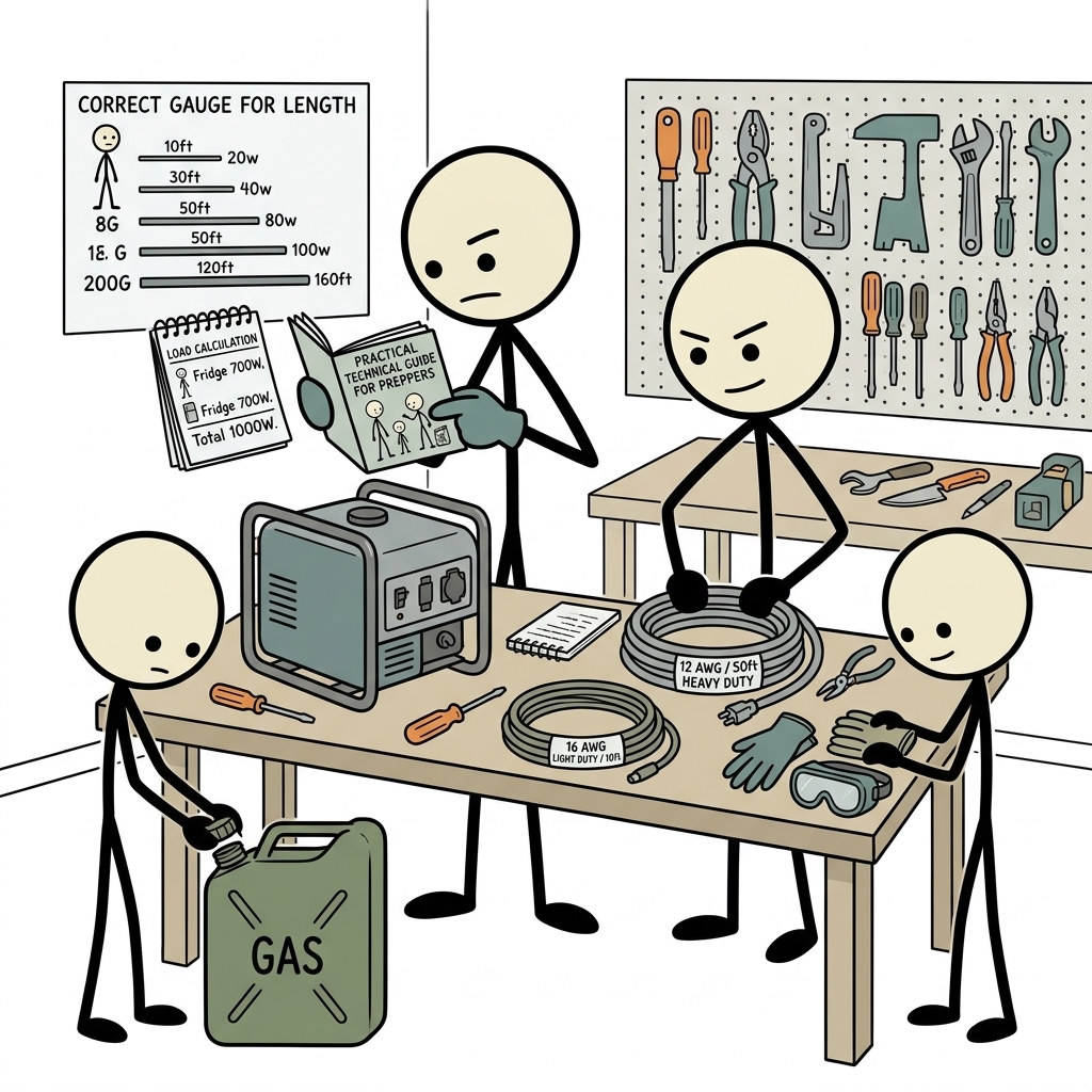
True emergency preparedness means abandoning guesswork in favor of precise empirical data. To engineer your emergency distribution network, build a tactical electrical inventory sheet. This audit must prioritize life-safety and asset-protection systems before convenience items.
To establish accurate values, locate the manufacturer’s technical data plate on each target appliance. This metal or foil placard is typically found on the rear panel, inside the door frame, or near the compressor housing. The data plate lists the device's operational voltage, frequency (60 Hz in North America), and either rated running wattage or operational amperage. If the placard only displays voltage and full-load amps (FLA), use the power formula ($V \times A$) to determine true continuous wattage.
Tactical Load Matrix for Critical Infrastructure
The table below provides baseline operational and starting wattage estimates for essential prepper infrastructure. Always verify your specific hardware using a digital energy meter (such as a Kill A Watt) or by reading the manufacturer's LRA specifications.
| Appliance / Equipment | Voltage | Running Watts | Starting / Surge Watts | Priority Tier |
|---|---|---|---|---|
| Deep Well Submersible Pump (1/2 HP) | 240V | 1,000 W | 2,500 W | Tier 1 (Critical) |
| Primary Sump Pump (1/3 HP) | 120V | 800 W | 1,800 W | Tier 1 (Critical) |
| Full-Size Refrigerator / Freezer | 120V | 150–250 W | 800–1,200 W | Tier 1 (Critical) |
| Medical Oxygen Concentrator | 120V | 350–600 W | 600–1,000 W | Tier 1 (Life-Safety) |
| Natural Gas / Propane Furnace Blower | 120V | 600 W | 1,500 W | Tier 2 (Sustainment) |
| Standalone Chest Freezer | 120V | 100–150 W | 500–800 W | Tier 2 (Sustainment) |
| HAM / Comms Base Station (Transmitting) | 120V | 150–250 W | 250 W | Tier 3 (Tactical) |
| LED Lighting String (Whole House) | 120V | 60–100 W | 100 W | Tier 3 (Tactical) |
Applying the NEC Continuous Load Standard
The National Fire Protection Association (NFPA) sets baseline safety standards through the National Electrical Code. One of its most foundational tenets is the continuous load rule (NEC Article 210.19/210.20): any load running continuously for three hours or more must not exceed 80% of the rated capacity of the circuit conductor or the power source.
If your portable generator is rated at 5,000 "running" or continuous watts, do not design a survival load plan exceeding 4,000 continuous watts ($5,000 \times 0.80 = 4,000$). Operating a generator perpetually at 95% to 100% capacity accelerates mechanical wear, raises total harmonic distortion (THD), causes engine bogging when inductive loads cycle on, and rapidly overheats internal alternator coils. Maintain that 20% buffer as an operational reserve for transient motor surges.
Understanding Wire Gauge (AWG) and Conductor Ampacity
Once you know your operating amperages, select the appropriate conductors to move that power. The cross-sectional diameter of electrical copper wire in North America is measured using the American Wire Gauge (AWG) system. The AWG scale works on an inverse logarithmic principle: as the gauge number decreases, the physical diameter and cross-sectional area of the copper wire increase.
A smaller gauge number signifies a thicker, heavier copper conductor capable of transporting more current with less internal electrical resistance. A 10 AWG wire has significantly more copper mass than a 16 AWG wire, allowing it to convey higher amperage without thermal degradation.
Ampacity Ratings for Extension Conductors
Ampacity is the maximum current, in amperes, that a conductor can carry continuously under the conditions of use without exceeding its temperature rating. If you exceed a conductor's rated ampacity, the resistance generates heat faster than the outer jacket can dissipate it. This process breaks down, softens, and ultimately melts the internal insulation, creating short circuits, phase-to-ground faults, and house fires.
- 16 AWG (Light Duty): Rated for a maximum of 10 Amps. Suitable only for small electronics, individual LED utility lamps, and phone chargers. Never use this gauge for motors, refrigeration, or space heating.
- 14 AWG (Medium Duty): Rated for a maximum of 15 Amps. Suitable for power tools, individual entertainment setups, and general-purpose lighting over short distances.
- 12 AWG (Heavy Duty): Rated for a maximum of 20 Amps. The absolute tactical baseline for emergency preparedness. Capable of handling high-draw kitchen appliances, sump pumps, and refrigerators.
- 10 AWG (Extra Heavy Duty): Rated for a maximum of 30 Amps. Essential for multi-outlet distribution trunk lines, RV 30A connections (TT-30), and feeding 120V/240V generator twist-lock receptacles (L14-30R).
- 8 AWG & 6 AWG (Industrial / Whole-Home): Rated for 40 to 55+ Amps. Reserved for 120V/240V 50-amp distribution lines (CS6365 or NEMA 14-50P) connected directly to manual transfer switch utility panels.
Deciphering Cable Jacket Designations
A proper heavy duty extension cord for generator applications is defined not just by the internal copper gauge, but by the outer jacket protecting those conductors from the elements. The Occupational Safety and Health Administration (OSHA) and the NEC use a standardized lettering code to classify cable jackets:
- S: Service Grade (severe-duty rated for general use, 600V rated).
- J: Junior Service (hard-service rated, flexible jacket limited to 300V residential usage).
- T: Thermoplastic (durable vinyl/plastic jacket, stiffens in sub-freezing temperatures).
- E: Elastomer (thermoplastic rubber; far more flexible in deep sub-zero conditions).
- O: Oil-resistant outer protective jacket.
- OO: Oil-resistant outer protective jacket and oil-resistant internal conductor insulation.
- W: Weather and Water-resistant (rated by UL for outdoor use, sunlight/UV resistance, and moisture immersion).
For cold-weather or storm-Survival Scenarioss, standard household vinyl cords (like cheap orange SPT or basic SJT cords) turn brittle and crack when exposed to sub-zero temperatures. For off-grid preparedness, insist on cables designated as SOOW or SJTW. An SOOW cord features an oil-resistant, ultra-flexible synthetic rubber jacket that stays flexible down to -40°F, ensuring reliable operation in severe blizzards and ice storms.
Voltage Drop: The Hidden Appliance Destroyer
Even if an extension cord is rated to carry the continuous amperage of your appliance, you cannot run that cord an arbitrary distance. Every linear foot of copper wire introduces electrical resistance to the circuit. When current flows against this internal resistance, a portion of the voltage converts into wasted heat energy. This physical phenomenon is known as voltage drop.
When voltage drops significantly over an excessively long line, the appliance on the receiving end receives less electrical potential than it requires. Ohm's Law demonstrates that if the voltage drops while the appliance's work output remains fixed, the running amperage must rise to compensate. This extra current overheats the motor windings in valuable appliances like refrigerators, well pumps, or medical gear, breaking down the internal winding insulation and causing early motor burnout.
The 3% Voltage Drop Rule
The National Electrical Code (NEC Article 210.19 FPN No. 4) recommends that steady-state voltage drop on branch circuits should never exceed 3% from the power source to the point of utilization. On a standard nominal 120-volt generator circuit, this allows for a maximum loss of just 3.6 volts:
$120\text{V} \times 0.03 = 3.6\text{V drop maximum (116.4V delivery threshold)}$
For non-sensitive, purely resistive heating elements or emergency incandescent lighting, a 5% maximum drop (down to 114V) is marginally acceptable. However, sensitive digital microprocessors, modern inverter refrigerators, and HVAC control boards will display system error faults or reset spontaneously when input voltage drops below 114V. You can calculate precise single-phase line voltage drop using the following electrical engineering formula:
$V_{\text{drop}} = \frac{2 \times K \times I \times L}{\text{CM}}$
Where:
- K: Direct current constant resistivity of copper (typically 12.9 ohms per circular mil-foot at operational temperatures).
- I: Circuit load current in Amperes.
- L: One-way length of the cable run in feet.
- CM: Circular mil area of the chosen conductor (e.g., 14 AWG = 4,110 CM; 12 AWG = 6,530 CM; 10 AWG = 10,380 CM).
Safe Generator Cord Length and Gauge Matrix
To keep calculations practical during an emergency, consult this reference guide for single-phase 120V distribution circuits. It balances generator cord wire gauge against safe generator cord length to maintain voltage drop at or below the critical 3% threshold.
| Load Current (Amps) | Continuous Watts (120V) | 25 Foot Run | 50 Foot Run | 75 Foot Run | 100 Foot Run |
|---|---|---|---|---|---|
| 5 Amps | 600 W | 16 AWG | 16 AWG | 14 AWG | 14 AWG |
| 10 Amps | 1,200 W | 14 AWG | 14 AWG | 12 AWG | 10 AWG |
| 15 Amps | 1,800 W | 14 AWG | 12 AWG | 10 AWG | 8 AWG |
| 20 Amps | 2,400 W | 12 AWG | 10 AWG | 8 AWG | 8 AWG |
| 30 Amps (120V) | 3,600 W | 10 AWG | 8 AWG | 6 AWG | 6 AWG |
Green = Optimal / Fully Compliant with 3% NEC limit; Yellow = Moderate Voltage Drop (Near 3% limit); Orange = Critical Voltage Drop (Exceeds safe limits for inductive compressors).
Tactical Distribution Architectures: Running Cords Safely
Choosing the right wire gauge is only part of the battle. How you physically route, protect, and manage high-amperage temporary distribution lines in hostile weather conditions directly determines the survivability of your setup.
The Coiled Cable Thermal Hazard
One of the most dangerous, widespread mistakes in field generator operation is leaving excess extension cord wrapped neatly on an industrial storage reel or stacked in loops on the ground while powering a load. When alternating electrical current flows through an insulated wire, it creates a surrounding magnetic field and dissipates heat proportional to $I^2 R$ (current squared multiplied by resistance).
When an extension cord remains coiled, it cannot vent this heat to the open air. The tightly bundled loops trap heat, acting as an air-core induction choke and thermal incubator. Within thirty minutes of running a continuous 12-to-15 amp load through a coiled 100-foot cord, the interior insulation core can exceed 200°F (93°C). The copper conductors will fuse together inside the jacket, creating a high-energy dead short that can ignite dry leaves, flooring, or melting vinyl jackets. Always flake out extension cords completely in wide, loose "S-curves" along the ground to ensure unobstructed convective cooling.
The Life-Safety Buffer: Carbon Monoxide Mitigation
The CDC and the CPSC state repeatedly that portable generators must never, under any circumstances, be operated inside a home, basement, crawlspace, garage, or partially enclosed porch. Deadly levels of invisible, odorless carbon monoxide (CO) can accumulate within minutes, permeating living spaces through wall penetrations, soffits, and window frames.
Your generator must sit a minimum of 20 feet away from any door, window, or HVAC air intake vent, with its exhaust pointed away from the structure. Factoring in this life-safety buffer confirms why using short 10-foot or 15-foot extension cords is physically impossible in a secure configuration. Your field layout must be planned around long, heavy-duty distribution runs capable of clearing this 20-foot perimeter while delivering safe line voltage inside.
Terminal Connections and Split
Frequently Asked Questions
What wire gauge (AWG) is safest for a portable generator extension cord?
A 10-gauge (AWG) or 12-gauge cord is recommended for most applications. Lower gauge numbers indicate thicker wire, which handles higher current and minimizes voltage drop over distance.
How does extension cord length affect generator power delivery?
Longer cords increase electrical resistance, leading to voltage drop and excessive heat generation. Keep cords as short as practical—ideally 50 to 100 feet—and step down to a thicker wire gauge for runs exceeding 50 feet.
Can I plug a generator into a regular wall outlet using a male-to-male cord?
No. This practice, called backfeeding, is illegal and extremely dangerous. It creates an immediate fire hazard and can backfeed power into utility lines, fatally electrocuting utility workers.
What cord rating jacket designations should I look for on generator cords?
Select heavy-duty outdoor-rated cords marked with ratings such as SJTW, STW, or SOOW, which indicate oil, moisture, weather, and abrasion resistance suitable for outdoor emergency use.
How do I calculate the maximum continuous load for an extension cord?
Multiply the cord amp rating by voltage (e.g., 20A x 120V = 2,400W), then apply the standard 80% continuous load safety margin (2,400W x 0.8 = 1,920W continuous limit) to prevent cord overheating.