⚡ Key Facts
- Widespread Reliance: According to the United States Geological Survey (USGS), more than 43 million Americans rely on private domestic wells for their daily drinking water and household sanitation.
- Extreme Inrush Demand: A standard deep-well submersible pump typically requires an inrush (starting) surge current that is 300% to 500% higher than its continuous running wattage, demanding careful sizing to prevent generator stall.
- Critical Water Baselines: The Federal Emergency Management Agency (FEMA) and the Centers for Disease Control and Prevention (CDC) advise storing at least one gallon of water per person per day for survival, but sustained hygiene, toilet flushing, and livestock care require 5 to 12 gallons per person daily.
- Voltage Requirements: More than 85% of modern residential submersible well pumps operate on a 240-volt single-phase split circuit, meaning a standard 120-volt portable generator cannot power them without specialized step-up transformers or panel-level integration.
- Code and Safety Compliance: National Electrical Code (NEC) Article 702 strictly mandates a mechanical or automatic transfer interlock to isolate generator power from grid infrastructure, preventing deadly utility backfeeding during grid restoration.
When high-impact weather patterns, ice storms, or regional grid failures sever municipal utility lines, rural and suburban households face an immediate secondary crisis that municipal residents rarely experience: total water loss. While modern plumbing conceals the mechanics, every drop of water drawn from a private domestic well relies entirely on an energized motor suspended hundreds of feet below the earth. Without a dependable well pump backup power strategy, a prolonged outage instantly cascades into a critical sanitation, hydration, and fire-defense emergency. Sizing, selecting, and safely integrating a generator for well pump operation is not a speculative task; it requires precise electrical engineering calculations, an understanding of motor physics, and strict adherence to electrical codes. For the practical checklist side, use the community emergency preparedness guide.
Understanding Residential Well Pump Anatomy and Electrical Characteristics
Before buying an emergency well water generator, you must diagnose the specific mechanical and electrical properties of your existing water system. Domestic wells generally rely on one of two pump configurations: shallow well jet pumps or deep well submersible pumps. Jet pumps are mounted above ground—typically inside a basement, utility closet, or pump house—and pull water from depths shallower than 25 feet. Submersible pumps are submerged deep within the well casing, suspended anywhere from 50 to more than 600 feet below grade, pushing water upward into the home. For the practical checklist side, use the neighborhood preparedness network.
Submersible systems dominate modern residential installations because of their efficiency, quiet operation, and immunity to surface freezing. However, because they must push column-weight water against atmospheric and hydrostatic head pressure, their power profiles are significantly more demanding. Submersible motors are sealed inside stainless steel cylindrical housings, operating in narrow boreholes where heat dissipation depends on cold groundwater flow. If a generator delivers substandard voltage or distorted sine waves, these motors can overheat rapidly without visual or audible cues above ground. For the practical checklist side, use the emergency communication plan.
Residential well pumps operate within two primary electrical architectures: 2-wire and 3-wire configurations. In a 2-wire system, the pump’s starting components—such as the centrifugal switch and capacitor—are sealed permanently inside the submerged motor housing. In a 3-wire configuration, these sensitive electromechanical components reside in an above-ground control box mounted on the wall near your pressure tank. Knowing which system you own is critical: 3-wire control boxes allow you to inspect, repair, and replace starting capacitors that might degrade under generator operation without pulling hundreds of feet of drop pipe from the well. For the practical checklist side, use the family emergency planning guide.
Operating Voltages: The 120V vs. 240V Division
Voltage dictates the type of generator required. While small, shallow jet pumps under 1/2 horsepower (HP) sometimes run on standard 120-volt circuits, the overwhelming majority of modern submersible pumps require a 240-volt, single-phase power supply. This eliminates entry-level 120V recreational generators from consideration, regardless of their total wattage capacity. For the practical checklist side, use the real-world emergency scenarios guide.
To run a 240V motor, your generator must feature a 120/240V selector switch or dedicated split-phase 240V receptacles (such as a NEMA L14-20R or L14-30R). Connecting a 240V pump to a 120V generator without a transformer will immediately trip breakers, burn out motor windings, or stall the engine. Checking the dedicated two-pole circuit breaker in your service panel or inspecting the well control box label confirms your pump's exact operating voltage.
The Physics of Inductive Pump Loads: Running Watts vs. Inrush Surge

Calculating the electrical demand of an electric motor requires distinguishing between resistive loads and inductive loads. Resistive loads, such as electric baseboard heaters, space heaters, and incandescent bulbs, convert electrical current directly into heat and light with near-constant resistance. When energized, resistive loads draw almost identical starting and running wattage. Inductive loads, which use electromagnetic fields to create mechanical motion, behave entirely differently.
An idle well pump motor provides almost zero back-electromotive force (counter-EMF) at the exact millisecond power is applied. To break the physical inertia of the heavy motor rotor, the pump impellers, and the suspended water column inside the drop pipe, the motor draws a violent burst of current known as Locked Rotor Amperage (LRA). Once the rotor reaches operational speed (usually within 200 to 500 milliseconds), the current plummets to its normal operating rate, designated as Full Load Amperage (FLA).
Homeowners often make the catastrophic mistake of purchasing an emergency generator sized strictly to the pump’s running watts. When the generator engages, the massive LRA demand instantly overwhelms the engine’s rotational momentum and saturates the alternator windings. The generator experiences a sharp voltage drop (brownout) and either stalls outright or trips its magnetic circuit breaker. Worse, sustained low-voltage conditions during an extended locked-rotor event can melt the winding insulation of your submerged motor, requiring thousands of dollars in mechanical extraction and replacement.
Motor Horsepower to Wattage Conversions
Electrically, 1 mechanical horsepower equals roughly 746 watts. However, electric motors operate at imperfect electrical efficiencies, typically between 60% and 85%, and possess a power factor (PF) varying from 0.75 to 0.90 under load. A 1 HP motor therefore does not consume just 746 watts of grid power; it often pulls 1,500 to 2,000 true operating volt-amps (VA) from an independent power source.
National Electrical Manufacturers Association (NEMA) code letters printed on the pump motor data plate establish the precise kilovolt-ampere (kVA) surge factor per horsepower. When this data plate is unreachable hundreds of feet down a well, standard electrical safety planning relies on a 3.5x to 4x surge multiplier applied to continuous running wattage to ensure adequate overhead for unassisted starting.
What Size Generator to Run a Well Pump: Step-by-Step Calculations
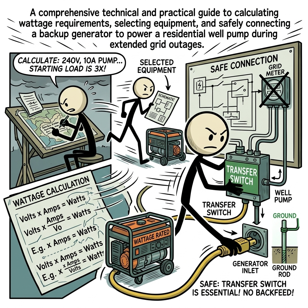
To determine what size generator to run a well pump on your property, you must execute a methodical three-step calculation based on electrical specifications derived from your control box, pump documentation, or service panel.
Step 1: Determine Full Load Amps (FLA) and Running Watts
Locate the running amperage on your pump control box or measure it with a true-RMS clamp meter around one of the hot conductors while the pump is running at pressure. Calculate running wattage using the basic single-phase power formula:
Running Watts = Voltage (V) × Running Amps (A) × Power Factor (PF)
Example: A standard 3/4 HP, 240V submersible pump pulls approximately 8.0 Full Load Amps with a typical 0.85 power factor.
240V × 8.0A × 0.85 PF = 1,632 Running Watts
Step 2: Calculate Locked Rotor Amperage (LRA) and Starting Surge
Determine starting demand by acquiring the motor's actual LRA from manufacturer documentation or using standard engineering multipliers. If the motor lists an LRA of 35 amps at 240 volts:
Surge Volt-Amps = Voltage (V) × Locked Rotor Amps (LRA)
240V × 35A = 8,400 Starting Surge Watts (Volt-Amps)
If LRA is unknown, multiply the running watts by a conservative surge multiplier of 3.5:
1,632 Running Watts × 3.5 = 5,712 Starting Surge Watts
Step 3: Account for Elevation and Fuel Derating
Combustion engines lose volumetric efficiency as atmospheric density drops. Internal combustion engines lose roughly 3.5% of their rated power for every 1,000 feet above sea level. Furthermore, operating a dual-fuel generator on propane (LPG) instead of gasoline reduces total continuous and peak output by approximately 10% to 15% due to lower energy density per unit volume. Always factor these ambient and chemical realities into your final baseline output requirements.
Standard Well Pump Electrical Sizing Matrix
The following reference table outlines typical electrical requirements for standard 240V residential submersible well pumps. These figures reflect averages across major motor manufacturers (such as Franklin Electric and Pentair) and include baseline safe generator capacities.
| Pump Motor Rating | Voltage | Running Amps (FLA) | Running Watts | Inrush Amps (LRA) | Starting Surge | Min. Generator Size |
|---|---|---|---|---|---|---|
| 1/3 HP | 120V / 240V | 6.2A / 3.1A | 750 W | 18A / 9A | 2,200 W | 3,500 W Peak |
| 1/2 HP | 240V | 6.0A | 1,000 W | 24A | 4,000 W | 5,000 W Peak |
| 3/4 HP | 240V | 8.0A | 1,500 W | 35A | 6,000 W | 7,500 W Peak |
| 1.0 HP | 240V | 9.8A | 2,000 W | 44A | 7,500 W | 9,000 W Peak |
| 1.5 HP | 240V | 13.0A | 2,700 W | 58A | 10,500 W | 12,000 W Peak |
Equipment Selection: Choosing the Right Generator for Well Pump Reliability
When selecting a generator for well pump emergency operations, output wattage is only one variable among several mission-critical parameters. The generator’s architecture, fuel delivery mechanism, and harmonic purity directly affect its field longevity and the survival of your well equipment.
Inverter Generators vs. Open-Frame Standard Generators
Traditional open-frame portable generators regulate output voltage through basic automatic voltage regulators (AVRs) and govern engine speed mechanically at 3,600 RPM. These conventional units are cost-effective workhorses, but they frequently produce high levels of Total Harmonic Distortion (THD)—often between 12% and 25%. While simple electric motors can tolerate dirty electrical sine waves, modern variable-frequency drive (VFD) well pumps, digital solid-state control boxes, and electronic pressure sensors degrade rapidly under high THD.
Modern closed-frame or open-frame inverter generators convert raw AC power to DC, then invert it electronically into a pure sine wave with less than 3% to 5% THD. Running well pump on generator power with ultra-low THD prevents the logic boards inside advanced pump control boxes from malfunctioning or locking out due to voltage wave corruption. If your system incorporates a constant-pressure VFD pump, an inverter generator or a high-end commercial generator with a clean-power alternator is strictly mandatory.
Fuel Autonomy: Gasoline, Propane, and Diesel
Grid collapse events documented by NOAA and FEMA routinely stretch beyond 72 hours, often lasting weeks in the wake of severe ice storms, hurricanes, or derecho events. Gasoline degrades quickly inside storage tanks, gumming up carburetors within three to six months unless stabilized with chemical additives. Additionally, local fuel station pumps require grid electricity to dispense fuel, creating severe distribution bottlenecks during regional blackouts.
Dual-fuel and tri-fuel generators configured for liquid propane (LPG) or natural gas (NG) offer superior long-term survival posture. Propane maintains an indefinite shelf life without degrading, does not gum carburetors, and draws from stationary 250- to 1,000-gallon residential storage tanks commonly installed in rural homes. Diesel generators offer exceptional fuel efficiency, unmatched low-end torque for handling massive inductive motor surges, and high reliability, making them the gold standard for dedicated, heavy-duty rural installations despite their higher initial cost.
Safe and Code-Compliant Connection Methods
Under no circumstances should any homeowner implement improper, ad-hoc wiring schemes to power a well pump during an emergency. The practice of "backfeeding"—using a male-to-male extension cord plugged from a generator into a domestic dryer outlet—is extraordinarily dangerous, illegal under the National Electrical Code (NEC), and carries extreme legal liability.
Backfeeding energizes the entire electrical panel and sends unregulated, transformed high-voltage current back onto the main utility lines. This exposes line technicians working to restore the grid miles away to lethal electrocution risks. Furthermore, if grid power is suddenly restored out of phase while your generator is backfeeding, the resulting phase collision will instantly vaporize the generator alternator, start a fire within the service panel, and destroy connected appliances.
Method 1: Manual Transfer Switch (MTS)
A hardwired Manual Transfer Switch installed beside the main breaker panel represents the safest, most reliable connection framework for running well pump on generator setups. An MTS features physically linked, double-throw switches that mechanically prevent utility power and generator power from connecting simultaneously. Transfer switches can be dedicated exclusively to critical circuits—such as the well pump, refrigeration, and heating circuits—or deployed as whole-house service disconnects.
Method 2: Generator Interlock Kit
For budget-conscious homeowners seeking broad flexibility, a panel-specific, mechanically engineered Interlock Kit provides a safe and NEC-compliant solution. An interlock plate slides over your service panel cover, allowing the generator breaker to turn on only after the main utility breaker is switched fully to the "OFF" position. This turns your entire breaker panel into a custom generator distribution hub. You simply turn off non-essential high-draw breakers, start the generator, flip the interlock, and engage the dedicated 240V well pump breaker.
Floating Neutral vs. Bonded Neutral: Resolving the Grounding Puzzle
A frequent source of installation failure involves generator neutral-ground bonding configurations. By code, an electrical system can have only one system bonding jumper connecting the neutral conductor to the earth grounding electrode system.
- Bonded Neutral Generators: The neutral wire is connected directly to the generator's metal frame. If connected to a standard home panel through a transfer switch that does not switch the neutral conductor, you create an illegal and hazardous parallel neutral path, causing ground-fault circuit interrupters (GFCI) to trip instantly.
- Floating Neutral Generators: The neutral conductor is isolated from the generator chassis. When connecting to a home’s service entrance panel via a typical interlock or transfer switch, the generator must have a floating neutral, allowing the home's single central bonding point inside the main panel to maintain system ground integrity.
Consult a licensed electrician to verify whether your emergency well water generator requires removal of the internal bonding jumper or the installation of a 3-pole, switched-neutral transfer switch.
Operational Protocols: Running, Cycling, and Load Management
Successfully running your well on emergency generator power requires an efficient operational rhythm rather than running the generator continuously 24 hours a day. Small engines under sustained, continuous loads burn excessive fuel, generate heavy mechanical wear, and demand frequent maintenance intervals (oil changes are typically required every 50 to 100 hours of runtime).
The Water Banking and Cycling Strategy
Instead of maintaining constant generator runtime simply to pressurize household lines, implement a strict "water banking" protocol. Run your emergency setup in scheduled, high-efficiency operational windows two to three times per day:
- Isolate all non-essential circuit breakers in your service panel, dedicating the generator's output primarily to the well pump.
- Start the generator, allow the engine to achieve thermal equilibrium for 3 to 5 minutes, and engage the transfer switch.
- Cycle the pump on to bring the pressure tank to its peak cut-out pressure (commonly 50 to 60 PSI).
- Draw domestic water to top off secondary reservoirs, sanitize kitchen supplies, fill clean water storage containers, and prep hygiene basins.
- Run concurrent, complementary tasks such as chilling household refrigeration units or charging communications and battery banks.
- Disengage the well pump circuit, allow the generator engine to idle cool for 2 to 3 minutes, and shut down to conserve fuel reserves.
Optimizing Pressure Tank Dynamics
A well’s pressure tank acts as a mechanical energy accumulator. Inside, an air bladder maintains compressed air that pushes water through your domestic plumbing without forcing the submerged motor to spin up for every minor faucet cycle. When operating on an emergency well water generator, the pressure tank is your greatest efficiency asset.
Check the pre-charge air pressure inside your empty pressure tank using an accurate tire gauge on the tank's Schrader valve once a year. The pre-charge air must be calibrated precisely 2 PSI below the pump’s mechanical pressure switch cut-in setting (e.g., a 40/60 PSI switch requires an empty tank air pre-charge of 38 PSI). If the pressure tank becomes waterlogged due to an internal bladder failure, the well pump will "short-cycle," turning on and off rapidly every few seconds whenever water is drawn. Short-cycling under generator power dramatically spikes fuel consumption and risks overheating motor windings due to repeated inrush events.
Mitigating High Inrush Loads: Soft Starters and VFDs
If sizing calculations reveal that your well pump requires a 10,000-watt generator solely to overcome brief starting surge amps, consider retrofitting an electronic pump motor soft starter. A soft starter is a solid-state unit installed between the power supply and the motor that limits initial inrush current by ramping up phase voltage smoothly rather than delivering an instantaneous shock load. Quality soft-start controllers can drop locked rotor amperage by 30% to 50%, allowing a modest, fuel-efficient 4,000-to-5,000-watt inverter generator to smoothly start a 1 HP submersible pump that would otherwise stall it.
Generator Maintenance and Outage Readiness Protocols
A backup power system remains purely theoretical until mechanical failure tests it during a freeze or severe storm. Reliable emergency water production demands routine inspection, strict fuel stewardship, and mechanical trial runs under simulated blackout conditions.
- Monthly Exercise Cycles: Exercise the generator monthly for 20 to 30 minutes under an actual electrical load. Running the engine dry without load allows internal moisture to accumulate inside the crankcase and leaves the alternator exciter circuits untested. Energize a pair of space heaters or run the well pump directly during tests to ensure excitation caps are functioning properly.
- Chemical Fuel Stabilization: If storing unleaded gasoline, treat fuel with high-grade marine-grade stabilizers immediately upon purchase. Stabilized gasoline stored in sealed, vapor-tight military-spec containers retains utility for up to 12 months; non-treated fuel degrades within 90 days, producing varnishes that foul carburetor jets during critical start procedures.
- Consumables Pre-positioning: Maintain a dedicated on-site maintenance locker alongside your generator. Store three replacement spark plugs, two air filters, four quarts of full-synthetic engine oil (5W-30 or 0W-30 for cold-climate starts), a high-quality spare oil filter (if equipped with a pressurized oil pump), and spare mechanical fuses matching your control box and generator panels.
- Exhaust and Carbon Monoxide Safety: The CDC consistently documents that carbon monoxide (CO) poisonings surge directly following major natural disasters. Position your portable generator at least 20 feet away from home envelopes, open windows, doors, and crawlspace vents. Ensure the engine exhaust points downwind and directly away from any living structures, and verify that battery-backed dual CO/smoke alarms are operational on every level of the home.
Securing Your Off-Grid Water Sovereignty
Water security is the foundational pillar of domestic survival. Without reliable water delivery, prolonged shelter-in-place strategies fail rapidly, forcing families to abandon secure properties during wider regional infrastructure failures. Securing a reliable generator for well pump operation bridges the critical divide between vulnerability and mechanical self-sufficiency. By accurately calculating full load and locked rotor requirements, choosing a generator engineered for continuous output and low total harmonic distortion, and installing a code-compliant transfer assembly, you eliminate guesswork. You establish an enduring, life-sustaining system that guarantees clean running water on demand, regardless of how long the regional utility grid remains offline.
Frequently Asked Questions
What size generator do I need to run a residential well pump?
Most residential well pumps (1/2 HP to 1 HP) require 1,000 to 2,000 running watts and 3,000 to 5,000 starting watts (surge). A generator rated for at least 5,000 to 6,500 starting watts is typically recommended.
Can I plug a well pump directly into a portable generator?
Generally no. Most submersible well pumps operate on 240-volt hardwired circuits, requiring a manual transfer switch, generator interlock kit, or a dedicated 240V inlet installed by a licensed electrician.
Why do well pumps require so much more wattage to start?
Well pumps use inductive electric motors that draw a surge of up to three times their standard running wattage for a few seconds to overcome mechanical inertia and start lifting water against gravity.
Can an inverter generator run a submersible well pump?
Yes, provided the inverter generator supplies 240-volt output and delivers enough peak surge capacity to clear the pump motor's initial locked-rotor amp requirement.
How can I prevent generator power fluctuations from damaging my well pump?
Choose a generator with low Total Harmonic Distortion (THD below 5%), ensure proper grounding, and install a motor control box with integrated surge protection.