⚡ Key Facts
- Infrastructure Vulnerability: The Federal Communications Commission (FCC) reported that during major disaster declarations like Hurricane Helene, over 70% of commercial cellular towers in the worst-hit counties failed within the first 48 hours due to power loss and severed backhaul.
- Antenna Efficiency Over Radios: A 5-watt handheld transceiver paired with an elevated, resonant half-wave antenna will outperform a 50-watt mobile radio feeding a mismatched, low-profile rubber duck antenna in both signal-to-noise ratio and range.
- NVIS Regional Domination: Near Vertical Incidence Skywave (NVIS) propagation on the 40-meter and 80-meter amateur bands bypasses terrain blockages, bridging tactical dead zones between 30 and 400 miles without repeaters or satellites.
- Electrical Hazard Exposure: According to the American Radio Relay League (ARRL) and OSHA data, contact with overhead utility lines remains the leading cause of fatal accidents during temporary antenna deployments, making clearance calculation your most critical safety procedure.
- Resonance Impact: Operating at a Standing Wave Ratio (SWR) above 3:1 reflects over 25% of your forward radio frequency energy back into the transmitter finals, triggering thermal rollback circuits and collapsing battery reserves when transmission matters most.
When catastrophic floods, severe ice storms, or cyber disruptions collapse commercial teleemergency communication plans, the digital grid vanishes in a matter of hours. During the aftermath of Hurricane Katrina and the devastating Appalachian inland flooding of 2024, emergency management agencies like FEMA and voluntary relief groups like the Red Cross relied directly on the Amateur Radio Emergency Service (ARES) to route medical evacuations, coordinate supply drops, and establish primary situational awareness. Yet, dozens of newly licensed operators discover a brutal truth during their first field crisis: the most sophisticated multi-band transceiver is merely an expensive paperweight without a properly engineered, deployed, and tuned antenna. Mastering your emergency ham radio antenna is not an academic exercise—it is the direct physical interface that determines whether your voice cuts through atmospheric noise or dies in the dirt.
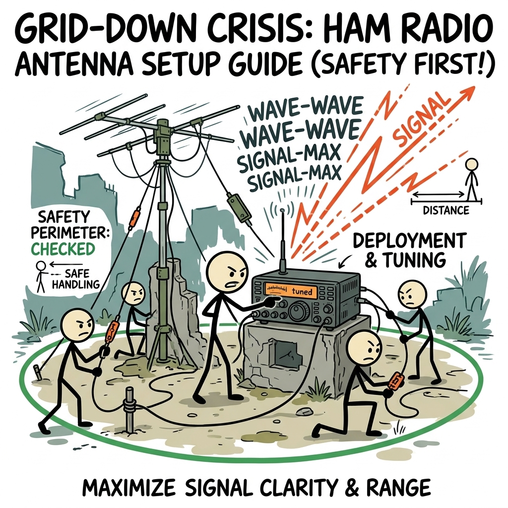
The Physics of Survival Propagation: Why Your Antenna Beats Transceiver Wattage
Many preppers fall into the high-power trap, believing that upgrading from a 5-watt handheld to a 100-watt mobile base station will automatically punch through terrain and heavy weather. In real-world physics, your antenna system dictates your Effective Radiated Power (ERP), receiver sensitivity, and noise floor rejection. An inefficient antenna dissipates expensive battery power as heat within lossy coax and mismatched loading coils, draining your power banks while transmitting a whisper. For the practical checklist side, use the neighborhood preparedness network.
Disaster-zone communication generally splits into two tactical categories: local/tactical line-of-sight and regional/continental skywave. Local tactical communications on VHF (Very High Frequency, 144–148 MHz) and UHF (Ultra High Frequency, 420–450 MHz) rely heavily on spatial elevation and clear Fresnel zones. On these frequencies, doubling your antenna’s height above average terrain yields significantly more signal gain than quadrupling your transmitter wattage, directly helping you improve ham radio reception across broken terrain. For the practical checklist side, use the family emergency planning guide.
Regional communications on HF (High Frequency, 3–30 MHz) require an understanding of ionospheric interaction governed by NOAA's Space Weather Prediction Center. During daylight hours, ionospheric D-layer absorption swallows lower frequencies, while nighttime recombination opens low-angle long-distance paths. Choosing the right emergency communication antennas requires tailoring your physical radiator to launch radio energy at the precise takeoff angle demanded by your tactical operational picture.
Near Vertical Incidence Skywave (NVIS): The Prepper's Grid-Down Lifeline
In mountainous terrain or densely forested valleys, traditional line-of-sight VHF signals crash directly into geographical obstacles, creating massive radio dead zones. Standard HF long-distance configurations fire radio waves toward the horizon at low angles (10 to 30 degrees), bouncing past your regional community and landing hundreds of miles away in an unusable skip zone. This creates a critical coverage gap between 30 and 300 miles—the exact footprint where community emergency preparedness guide groups, county emergency operations centers, and bug-out retreats typically operate.
Near Vertical Incidence Skywave solves this tactical dilemma by radiating signals almost straight up (70 to 90 degrees) into the ionospheric F-layer, reflecting them back down in an umbrella-shaped pattern that covers your immediate region without skip zones. You achieve NVIS propagation by deploying horizontal dipoles or end-fed wires between 0.1 and 0.25 wavelengths off the ground—typically just 7 to 12 feet high for the 40-meter band. This radically low profile eliminates the need for towering masts, reduces lightning vulnerability, and hides your operating position from visual sightlines.
Selecting the Right Emergency Ham Radio Antenna for Your Mission
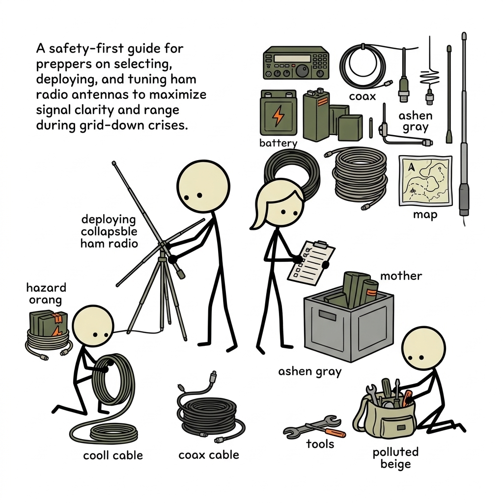
No single antenna excels across every frequency band or tactical environment. A robust prepper ham radio setup incorporates dedicated options for immediate rapid-deployment patrol work, semi-permanent base stations, and high-gain point-to-point links. Selecting the optimal system involves balancing structural survivability, packing volume, deployment speed, and frequency agility.
Tactical VHF/UHF Antennas: Beyond the Stock Rubber Duck
The flexible "rubber duck" antenna included with modern handheld transceivers is an electrically shortened, highly compromised compromise. Its internal coiled radiator exhibits high loss, zero gain, and poor grounding, turning more than 80% of your handheld's milliwatts into ambient heat. To bridge real tactical distances in emergencies, upgrade your portable deployment kit with proven field designs:
- Roll-Up 300-Ohm Slim Jim / J-Pole: Built from heavy-duty twin-lead ladder line, these flexible antennas roll into a pocket-sized pouch and deploy in seconds by hoisting them into a tree branch with paracord. They offer an omnidirectional radiation pattern, a significantly lower takeoff angle than a standard quarter-wave whip, and an immediate 3 to 6 dB boost over stock antennas without requiring a counterpoise.
- Telescoping Half-Wave Whips: Unlike quarter-wave whips that demand an effective chassis ground (often lacking on plastic-bodied handhelds), an end-fed half-wave whip operates independently of your radio body, dramatically cutting ground-loss resistance and stabilizing reception while moving.
- Portable Directional Yagi-Uda: For punching through dense RF interference or reaching distant repeaters run by local ARES or FEMA teams, a break-down 3-element tape-measure or aluminum Yagi provides high forward gain (up to 7 dBd) and deep side-null rejection to silence co-channel interference.
HF Wire Antennas: The Gold Standard for Resilience
When infrastructure collapses nationwide, high-frequency wire antennas become your primary link for monitoring USGS earthquake bulletins, NOAA maritime warnings, and national emergency traffic. Commercial steel towers will not survive Category 4 hurricane winds or severe freezing rain, but field-expedient wire designs survive, adapt, and repair easily using common field supplies.
The End-Fed Half-Wave (EFHW) has rapidly emerged as the quintessential prepper antenna. Utilizing a broadband 49:1 matching transformer (Unun), a multi-band EFHW cut to approximately 66 feet can resonate natively on 40, 20, 15, and 10 meters without an antenna tuner. Because it feeds at high impedance from the terminal end rather than the center, you can attach the matching box near the ground at your operating position and run the single wire up into an inverted-V, sloper, or horizontal configuration, dramatically cutting setup time in freezing rain or darkness.
The traditional Center-Fed Dipole remains the lowest-noise baseline across the amateur service. Cut to a half-wavelength using the standard field formula (Length in feet = 468 / Frequency in MHz), a resonant dipole delivers predictable, clean performance across local and regional channels. When fed with balanced ladder line through a wide-range balanced tuner, a center-fed doublet becomes an indestructible, multi-band survival antenna capable of handling extreme RF mismatches without heating up lossy coaxial jackets.
Deploying in Austere Conditions: Rigging, Anchoring, and Terrain
Operating in an austere environment means working without level roofs, manicured lawns, or pre-installed mounting brackets. Your physical rigging technique determines whether your emergency ham radio antenna survives overnight gale-force gusts or snaps, dropping your station off the air during critical operations.
Mastering the Arborist Throw Line
Trees are nature’s antenna masts, but attempting to heave an antenna wire over a 50-foot pine branch by hand invites tangled coax, snapped insulators, and wasted energy. Keep an arborist-grade slick line setup in your communications go-bag essentials guide: a 12-to-16-ounce weighted cordura throw bag paired with 150 feet of slick, high-visibility 2mm polyethylene or Dyneema throw line.
Inspect the target branch carefully before launching. Avoid dead limbs ("widow-makers") that can drop on your head during line retrieval or snap under the mechanical load of ice-coated antenna wires. Once the slick line clears the crotch of a healthy hardwood branch, tie off your 550 paracord or high-tensile mast rope and pull it back over, creating a heavy-duty hoisting halyard that stays rigged for the duration of the deployment.
Strain Relief and Environmental Flexing
Never tie antenna wire rigidly between two living trees. As wind moves through the canopy, trunks sway out of phase by several feet; an unyielding wire antenna will snap cleanly at the solder points or pull down your matching transformer. Always incorporate mechanical strain relief into your rigging plan:
- Counterweight Pulleys: Anchor the non-driven end of your wire through an inexpensive marine pulley, suspending an 8-to-12-pound weight (such as a canvas bag filled with local gravel) a few feet above the ground. As the trees sway, the weight moves vertically, maintaining uniform tension without overstressing the copper conductor.
- Bungee/Shock Cord Buffers: For rapid temporary deployments, insert marine-grade UV-resistant shock cords or heavy rubber snubbers between your end-insulators and tree anchors to absorb sudden wind gusts and ice loading.
- Drip Loops: Always configure a physical downward loop in your coaxial cable right before it enters your shelter or radio chassis. Water tracking along the jacket drops off at the low point rather than running directly into expensive connectors and moisture-sensitive transceivers.
Field Tuning and Resonance: The Life-or-Death of SWR
Deploying a wire in the trees is only half the battle; real-world environments alter the electrical characteristics of every antenna. Ground conductivity, soil moisture, proximity to wet foliage, and nearby metallic structures directly shift the resonant frequency and input impedance of your system. To protect your gear and maximize transmission range, you must measure and adjust your antenna once it is suspended in its operating position.
Demystifying Standing Wave Ratio (SWR)
Standing Wave Ratio measures the impedance match between your radio’s output circuit (standardized at 50 ohms resistive) and the combined transmission line and antenna system. When impedance matches perfectly, your SWR reads 1:1, meaning 100% of the forward power transfers to the antenna to be radiated into the ether.
| SWR Reading | Reflected Power | System Efficiency | Operational Action Required |
|---|---|---|---|
| 1.0:1 – 1.5:1 | 0% – 4% | Ideal (96%–100%) | Optimal performance; zero thermal risk to radio finals. |
| 1.6:1 – 2.0:1 | 5% – 11% | Acceptable (89%–95%) | Usable in emergency operations without modification; full power safe. |
| 2.1:1 – 3.0:1 | 12% – 25% | Degraded (75%–88%) | Modern radios begin thermal throttling; tune elements or activate tuner. |
| > 3.0:1 | > 25% | Dangerous (<75%) | Cease transmission. High voltage/current nodes risk puncturing final transistors. |
When SWR exceeds 2.5:1, the output transistors inside modern solid-state transceivers heat up rapidly. To protect sensitive gallium arsenide or silicon field-effect transistors from catastrophic breakdown, internal protection circuitry automatically throttles down your transmit wattage—often dropping a 100-watt station down to 20 watts or less without sounding an audible alarm. You might assume your signal is blanketing the county when, in reality, your system has throttled output to preserve its own electronics.
Field Diagnostic Tools: NanoVNA vs. SWR Meter
The traditional cross-needle SWR meter is reliable, but it requires you to transmit an active RF carrier on the air to take a reading. In an emergency, broadcasting uncoordinated test carriers ties up critical distress frequencies and risks damaging your final amplifiers if the antenna is accidentally open or shorted.
Every serious ham radio antenna guide now points toward modern Vector Network Analyzers, such as the pocket-sized NanoVNA. These lightweight, battery-operated tools inject a harmless, milliwatt-level signal into your antenna system across a broad frequency sweep. Within three seconds, the graphical display plots your exact resonant point, system impedance (R + jX), and return loss across the entire band without transmitting a disruptive signal on the air. If your dipoles show resonance at 6.8 MHz instead of the targeted 7.2 MHz, the analyzer tells you instantly that your physical wire is cut too long and needs shortening by precisely calculated inches.
Pruning Wire for True Resonance in the Mud
An antenna tuner (transmatch) does not tune your antenna; it merely transforms the impedance at the radio end of your coax line so your transmitter stays happy. The feedline between your tuner and the mismatched antenna still experiences destructive high standing waves, dielectric stress, and excessive signal loss. Whenever field conditions allow, achieve true physical resonance at the wire itself using these field steps:
- Deploy your wire slightly longer than theoretical calculations dictate (add 4 to 6 inches to each leg of a dipole or the end of an EFHW).
- Take an initial sweep with your antenna analyzer to locate the frequency of lowest SWR. If the minimum SWR dips below your desired operational frequency, your antenna is electrically too long; if it dips above, the antenna is too short.
- Never cut the excess wire immediately. Instead, loosen the terminal insulator, fold the end of the wire back over itself, and twist it snugly. Electrically, the folded wire acts as if it were trimmed to the fold point, but it preserves your copper should you need to re-lengthen the antenna when relocating to dry soil or changing operating bands.
- Retest the sweep. Once the lowest SWR centers over your primary emergency net frequencies (such as your regional ARES net or state emergency management channel), secure the folded tail with high-grade electrical tape.
Safety First: High Voltage, Lightning, and Structural Hazards
Under disaster conditions, adrenaline and operational urgency create dangerous blind spots. The National Fire Protection Association (NFPA) and the ARRL document consistent injuries and fatalities every year caused by improper, hurried antenna work. Antenna safety is not a secondary checkbox; it is the non-negotiable operational boundary that keeps you alive to communicate.
The Lethal Threat: Overhead Utility Lines
Overhead high-voltage distribution lines are quiet killers. A sagging 7,200-volt primary distribution line looks remarkably benign against an overcast sky, especially when downed trees and storm debris obscure right-of-ways. If a wire antenna, fiberglass mast, or paracord halyard touches an energized power conductor, lethally high currents track straight down the wet line through your hands to earth ground.
Follow the rigid 150% Height Safety Rule: Measure the total height of your antenna structure or wire span, multiply that value by 1.5, and ensure that no portion of your antenna system, support lines, or guy wires can swing within that distance of any utility pole or overhead wire. If a 30-foot mast collapses in a sudden squall, it must fall cleanly to the earth without grazing electrical infrastructure. Always assume that all downed lines are hot, even during wide-scale blackout events, because residential backfeeding from improperly installed home survival generators can instantly energize local distribution lines without warning.
Static Discharge and Lightning Mitigation
A direct lightning strike contains hundreds of thousands of amperes and will vaporize standard amateur antennas regardless of your grounding system. However, direct strikes are rare compared to the real everyday enemy: induced static accumulation and nearby cloud-to-ground electrostatic fields. High winds blowing dust, dry snow, or rain across an ungrounded wire antenna build up thousands of volts of static charge—often visible as rhythmic sparks jumping across an open PL-259 connector directly inside your radio room.
To safely bleed static energy before it destroys your radio’s sensitive front-end receiver diodes, install a robust grounding system modeled on the National Electrical Code (NEC Article 810):
- Gas Discharge Tube (GDT) Arrestors: Mount high-quality lightning arrestors (such as PolyPhaser or Alpha Delta) outside your shelter where the feedline enters. The internal gas tube fires in nanoseconds when voltages exceed normal levels, dumping electrostatic spikes harmlessly into the earth.
- Dedicated Earth Grounding Rods: Drive an 8-foot copper-clad steel ground rod into undisturbed soil right at the entry point. In rocky or frozen ground where deep driving is impossible, deploy a star-pattern radial field of bare heavy-gauge copper wire laid flat on the ground to diffuse static charges across a broad surface area.
- Single-Point Ground Bonding: If your field base draws AC power from an auxiliary generator or solar inverter, your antenna entrance ground rod must be mechanically bonded to the electrical system ground using heavy #6 AWG copper conductor. Unequal ground potentials between distinct grounding rods create deadly ground loops that route high-energy surges straight through your radio chassis.
Radio Frequency (RF) Exposure and Burn Hazards
Emergency operators often overlook the physical dangers of near-field radio frequency radiation. The high-impedance ends of half-wave dipoles and end-fed antennas carry several thousand volts of RF potential during a 100-watt transmission. Contact with an energized antenna element causes severe, deep-tissue RF burns that destroy skin and muscle without triggering a muscular shock reflex.
Ensure that all wire antennas, especially low-slung NVIS configurations, are suspended well out of reach of children, domestic animals, and field personnel. Maintain at least an 8-to-10-foot vertical clearance for any horizontal wire segment. When running mobile or tactical pedestrian gear, maintain the minimum separation distances mandated by FCC Part 97 RF exposure rules, keeping directional antennas aimed well away from populated living areas and camp perimeters.
Building an Indestructible Prepper Ham Radio Setup
True operational reliability in grid-down scenarios comes down to the quality of your consumables and connective hardware. A pristine radio connected through cheap, weathered coaxial cable will fail just as surely as a broken transceiver. Construct your portable antenna kit using components engineered to endure extreme temperature shifts, heavy UV radiation, and repeated field deployments.
Feedline Strategy: Attenuation vs. Portability
Coaxial cable choice is an engineering tradeoff between physical bulk and signal loss. Signal loss increases significantly with operational frequency and cable length. Understanding the decibel (dB) loss characteristics of common coax lines allows you to deploy the correct cable for your tactical posture:
- RG-58A/U: Thin, light, and highly flexible, RG-58 is an acceptable choice for short runs (under 30 feet) on HF bands or close-quarters tactical VHF field operations. However, at UHF frequencies (440 MHz), RG-58 loses nearly 10 dB per 100 feet, which swallows 90% of your transmit power before it ever reaches the antenna radiator.
- RG-8X (Mini-8): The optimal compromise for portable field kits. It matches the flexibility of lighter cables while providing substantially lower signal loss, making it ideal for HF dipoles and 50-foot runs up into tree-mounted antennas.
- LMR-400 / Bury-Flex: The standard for permanent base station feeds and fixed-position VHF/UHF tactical operations. With an exceptionally low loss profile and solid internal foil shielding, it delivers virtually all your radio's power to the sky, though its stiff physical bend radius makes it cumbersome for rapid bug-out go-bags.
Weatherproofing Field Connections
Moisture ingress is the silent killer of radio systems. Once water enters an unsealed coaxial connector, capillary action draws moisture yards deep into the braided shield, oxidizing the copper, throwing system impedance wildly out of spec, and permanently destroying the cable. Standard vinyl electrical tape will fail; its adhesive dissolves in rain and turns brittle under direct solar ultraviolet radiation.
Seal every exterior RF connection using the industry-standard Three-Layer Weatherproofing Protocol. First, tightly wrap the mated PL-259 or N-connector with a continuous layer of high-grade electrical tape (such as Scotch Super 33+) laid sticky-side up to protect the metal housing from sticky residue. Second, mold an aggressive layer of butyl rubber or self-amalgamating silicone mastic tape completely around the junction, stretching it to twice its resting length to fuse it into a solid, impenetrable moisture barrier. Third, cover the mastic completely with two overlapping, tightly stretched layers of UV-resistant vinyl tape (such as Scotch 88), wrapping shingle-style from bottom to top to shed cascading rainwater naturally.
The Rapid-Deploy Emergency Antenna Go-Bag
Store your antenna components in a dedicated, durable canvas deployment bag separate from your primary transceiver, ensuring you can quickly hand the kit to a family member or team scout for rapid deployment. Your deployable antenna field kit should include:
- One 40-to-10-meter broadband End-Fed Half-Wave (EFHW) antenna with integrated 49:1 Unun (rated for at least 100W PEP).
- One rollup 2m/70cm ladder-line J-pole with 25 feet of integrated RG-8X feedline terminating in a BNC male connection.
- 50 feet of high-grade RG-8X coaxial feedline with factory-crimped, silver-plated PL-259 or BNC connectors.
- A curated RF adapter kit (BNC-to-PL259, SMA-female to BNC, SMA-male to BNC, and PL-259 barrel connectors) to interface your antenna systems with any volunteer's radio hardware.
- 150 feet of high-visibility 2mm UHMWPE slick arborist line with a 12-ounce aerodynamic throw weight.
- 200 feet of rot-proof, low-stretch Mil-Spec 550 paracord for permanent guy lines and halyards.
- A NanoVNA or compact battery-operated antenna analyzer, calibrated and pre-programmed with your primary emergency net sweeps.
- Two heavy-duty screw-in ground anchors or military-style spiral earth stakes for guying and static dissipation fields.
- A field weatherproofing kit: one roll of self-amalgamating tape, two rolls of Scotch Super 88, and a tube of dielectric grease.
During wide-scale infrastructure collapse, clear and dependable communication is your most valuable survival asset. By building resilient antenna platforms, respecting high-voltage boundaries, and understanding how to tune your elements for true electrical resonance, you protect your station electronics and guarantee that your critical traffic reaches its destination. Take your gear into the field now, test it under adverse weather conditions, and turn these fundamental radio engineering practices into second-nature operational instincts before the grid goes silent.
Frequently Asked Questions
What is the best quick antenna upgrade for a handheld ham radio during an emergency?
Replacing the stock factory 'rubber duck' antenna with a tuned 15-to-19-inch flexible whip or connecting to an elevated roll-up slim-jim/J-pole antenna significantly improves VHF/UHF signal clarity and reception distance.
How does antenna elevation affect emergency radio communications?
VHF and UHF frequencies rely primarily on line-of-sight propagation, meaning elevating an antenna even 10 to 20 feet using a mast or tree branch dramatically expands reception range and clears ground obstructions.
What key safety hazards should be avoided when setting up a temporary antenna?
Never deploy an antenna near overhead power lines, ensure a safe fall radius equal to or greater than the antenna's height, and avoid operating or raising wire antennas during active lightning storms.
Why is an SWR meter important when building or adjusting emergency antennas?
A Standing Wave Ratio (SWR) meter measures the impedance match between the radio and antenna; an SWR under 2:1 ensures efficient power transmission and prevents overheating or damaging the radio's transmitter.
Can I use random wire to receive emergency broadcasts without damaging my radio?
Yes, connecting a long wire to your receiver can drastically enhance reception without risk, but you must avoid transmitting on non-resonant wire antennas unless an appropriate antenna tuner is used.