⚡ Key Facts
- Grid Vulnerability: According to the U.S. Energy Information Administration (EIA), the average American electricity customer experiences over seven hours of power interruptions annually, with major weather events multiplying that duration significantly. For the practical checklist side, use the community emergency preparedness guide.
- Backfeeding Hazards: Connecting a portable generator directly to a home wall outlet without an isolated switch is illegal under the National Electrical Code (NEC Article 702) because it backfeeds lethal high-voltage power into neighborhood preparedness network utility lines, endangering line workers and neighbors.
- Carbon Monoxide Risks: The Centers for Disease Control and Prevention (CDC) reports that over 400 Americans die each year from unintentional carbon monoxide (CO) poisoning, with portable generators operating too close to home openings serving as a leading cause during post-storm blackouts. For the practical checklist side, use the emergency communication plan.
- Sizing Realities: Induction motors—such as those found in well pumps, refrigerators, and furnace blowers—require between two and three times their running wattage just to start (Locked Rotor Amps), making dynamic load planning essential. For the practical checklist side, use the family emergency planning guide.
- Safety Standard: A properly installed manual transfer switch isolates critical circuits at the subpanel level, keeping utility neutrals and hot legs separated, ensuring 100% code compliance and seamless transition back to utility power.
When violent weather or infrastructure failures sever your connection to the commercial electrical grid, the difference between an inconvenient evening and a compounding domestic crisis comes down to preparation. According to data from the National Oceanic and Atmospheric Administration (NOAA) and the Federal Emergency Management Agency (FEMA), multi-day outages following winter storms, hurricanes, and severe convective systems are on the rise across North America. In these prolonged blackout scenarios, hauling dozens of daisy-chained extension cords through cracked windows is not merely inefficient—it introduces severe trip hazards, compromises your home's thermal envelope, and creates dangerous points of carbon monoxide ingress.
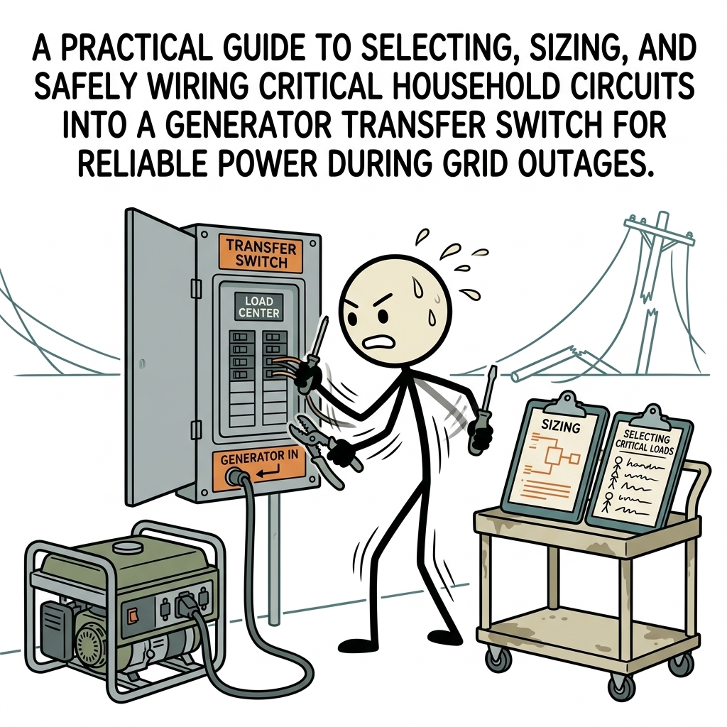
The definitive solution for clean, organized, and code-compliant residential resilience is a dedicated transfer switch. By routing designated branch circuits directly from your main electrical panel through an isolated transfer mechanism, you can safely energize your home’s mission-critical infrastructure with a flip of a toggle. This generator transfer switch guide walks you through every phase of the engineering process: identifying and sizing your essential circuits for power outages, balancing electrical legs, understanding neutral bonding rules, and executing a professional-grade manual transfer switch setup.
Why a Transfer Switch is Non-Negotiable for Emergency Home Power Backup
In an emergency, speed and safety must coexist. While many homeowners initially rely on heavy-duty extension cords during short blackouts, this approach breaks down quickly when you must power hardwired appliances. Systems like gas furnace blowers, domestic water well pumps, hardwired sewage ejectors, and municipal water pressure boosters cannot simply be plugged into a standard three-prong cord. They are hardwired into the home’s primary distribution panel.
A manual transfer switch (MTS) or mechanically interlocked transfer panel permanently bridges this gap. It provides a hardened, code-compliant connection point that completely isolates your backup power source from the incoming utility lines. This isolation prevents the dangerous phenomenon known as "backfeeding." Pair the electrical plan with a household-wide emergency preparedness plan so roles, supplies, and shutdown steps are already clear before an outage.
The Danger of Backfeeding
Backfeeding occurs when a generator is connected directly to a home circuit via a rogue double-male cord plugged into a standard wall receptacle. When this happens, current travels backward through your panel and into the utility distribution transformer on your street. That transformer does not know the difference between grid power and generator power; it steps that 120V or 240V current back up to 7,200 to 14,400 volts.
This transforms neighborhood power lines into lethal hazards for utility line crews working down the street to restore the grid. It also poses severe fire risks to your own home and can destroy your generator the second utility power surges back onto the line out of phase. Installing an emergency home power backup system with an approved transfer switch eliminates backfeed risk entirely through mechanical interlocks that make it physical impossible for utility and generator power to bridge simultaneously.
Manual Transfer Switch vs. Panel Interlock Kit
When establishing your backup setup, you generally have two primary pathways:
- Multi-Circuit Transfer Switch: A dedicated subpanel containing a predetermined number of circuit switches (typically 6, 8, or 10 circuits). Each switch has three positions: LINE (utility), OFF, and GEN (generator). This design allows you to selectively power individual critical branch circuits while leaving the rest of the main panel dead, preventing accidental generator overloads.
- Mechanical Panel Interlock Kit: A custom steel or aluminum sliding plate installed directly onto the face of your existing main service panel. The plate mechanically prevents the generator double-pole breaker from being turned on until the main utility disconnect breaker is switched off. This allows you to selectively turn on virtually any breaker in your entire panel, provided you actively manage the total electrical load yourself.
Phase 1: Selecting Your Essential Circuits for Power Outages
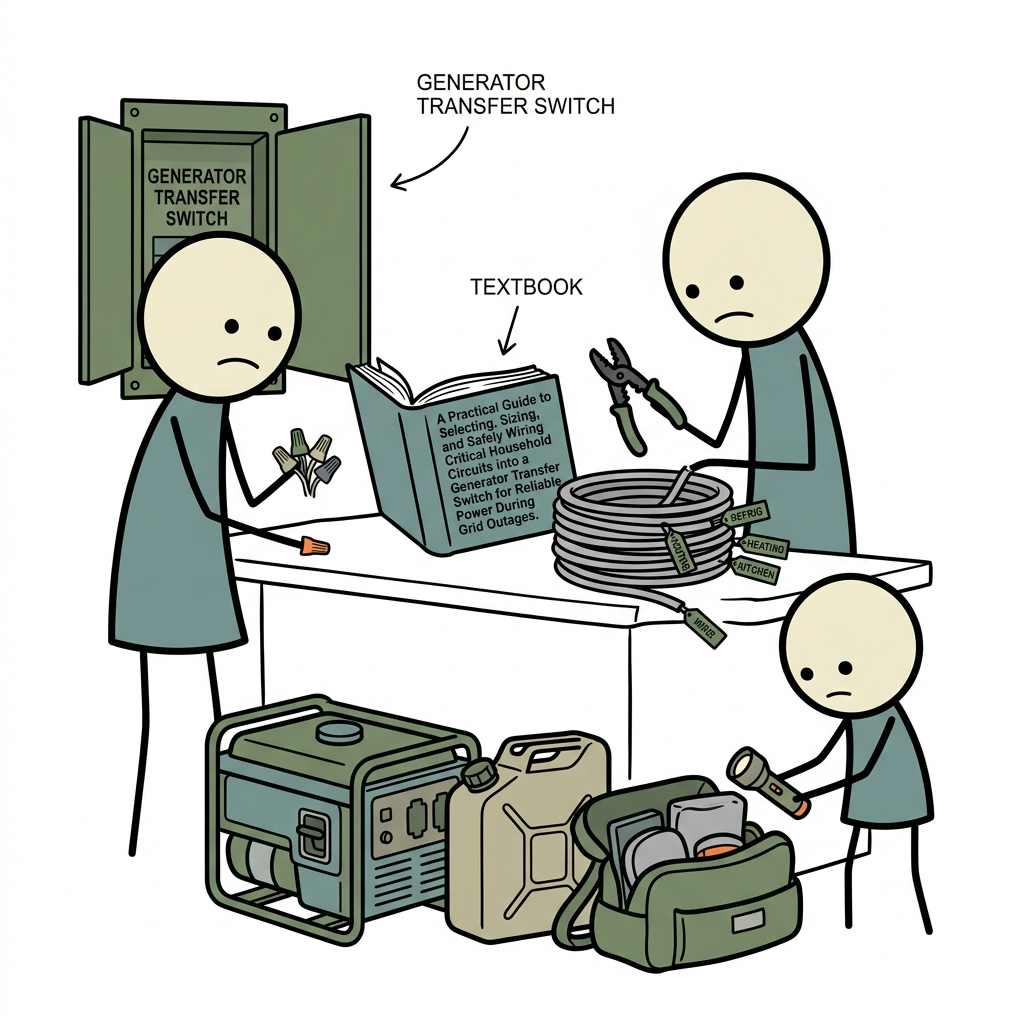
The cardinal mistake in emergency power planning is attempting to run the modern American household as if the grid were still functioning. Central air conditioning units, electric clothes dryers, electric water heaters, and double ovens consume enormous amounts of energy. Sizing a portable generator and transfer system to carry those resistive loads demands massive machines that burn 2 to 4 gallons of fuel per hour—a logistical nightmare during an extended disaster when local fuel stations may be without power.
Instead, apply a disciplined triage method. Prioritize life safety, property preservation, and basic human comfort. When choosing the backup circuits your generator will feed, focus on these five core pillars:
1. Life Safety and Medical Equipment
Any medical device requiring continuous power—such as oxygen concentrators, continuous positive airway pressure (CPAP) machines, or home dialysis equipment—must reside on your top-tier circuit. If you have medical needs on a dedicated bedroom branch, that breaker must be mapped directly to your transfer switch.
2. Potable Water and Sanitation Infrastructure
If your home relies on a municipal Water Calculator, your water pressure typically persists during a power outage. However, rural and suburban households dependent on deep-well submersible pumps require a 240-volt circuit to drive the pump motor. Without this circuit, you have no drinking water, no functioning toilets, and no firefighting reserves. Similarly, properties with basements vulnerable to hydrostatic flooding must prioritize the sump pump circuit, while homes with below-grade plumbing fixtures require the sewage ejector pump circuit.
3. Food Preservation and Refrigeration
The Red Cross notes that food kept in an unpowered, closed refrigerator begins spoiling after only four hours, while a full freezer maintains safe temperatures for roughly 48 hours. Mapping your primary kitchen refrigerator and secondary chest freezer preserves hundreds of dollars of perishable supplies and safeguards against foodborne pathogens during protracted grid disruptions. Build that circuit list alongside your water and food storage plan so your backup power protects the supplies that matter most.
4. Environmental Climate Control (Heating Systems)
While powering an electric furnace or whole-home heat pump via a standard portable generator is rarely practical, modern high-efficiency natural gas, propane, and fuel oil heating systems use very little electricity. The primary load is a 120-volt blower motor or hydronic circulation pump, which draws between 400 and 900 watts. Maintaining this circuit prevents hypothermia in freezing conditions and stops water pipes from bursting inside your walls, averting tens of thousands of dollars in structural damage.
5. Communications, Strategic Lighting, and Security
Navigating a dark home in an emergency increases fall risks, while isolation amplifies stress. Dedicate one to two 15-amp lighting circuits to cover the central living area, primary bathroom, and kitchen workspace. Modern LED lighting draws negligible wattage—often less than 10 watts per fixture. Finally, include the circuit that powers your internet modem, Wi-Fi router, and mobile device charging station to maintain real-time access to emergency broadcasts from the National Weather Service (NWS) and local civil defense authorities. Keep a battery-powered backup and practice the alert routine in your emergency radio plan for when broadband and cellular networks fail.
Phase 2: Load Sizing Calculations (Running vs. Starting Watts)
Electrical loads fall into two broad engineering classes: resistive loads and inductive loads. Mastering the difference between them is critical when choosing your transfer switch capacity and matching it to your generator's output profile.
Resistive vs. Inductive Loads
Resistive loads convert electricity into heat or light through direct resistance (such as incandescent light bulbs, toasters, and space heaters). These loads require the exact same amount of wattage to start as they do to run continuously. A 1,200-watt hair dryer draws 1,200 watts the millisecond it is switched on and keeps drawing 1,200 watts until turned off.
Inductive loads contain electromagnetic windings and electric motors (found in refrigerators, air compressors, sump pumps, well pumps, and furnace blowers). When an induction motor is stationary and power is applied, it draws a sudden, intense inrush of current called Locked Rotor Amps (LRA) to establish its magnetic field and overcome mechanical inertia. This startup surge can last from a fraction of a second to several seconds, demanding anywhere from two to three times the motor's nominal continuous running watts (Rated Load Amps).
| Critical Appliance / Load | Nominal Voltage | Typical Running Watts | Typical Starting (Surge) Watts | Priority Tier |
|---|---|---|---|---|
| Submersible Well Pump (1/2 HP) | 240V | 1,050 W | 2,200–3,000 W | Critical / High |
| Sump Pump (1/2 HP) | 120V | 800 W | 2,100 W | Critical / Seasonal |
| Gas/Oil Furnace Blower Motor | 120V | 600 W | 1,500 W | Critical / Life Safety |
| Kitchen Refrigerator/Freezer | 120V | 200–400 W | 1,200 W | Sustenance |
| Chest Freezer (Standalone) | 120V | 150 W | 800 W | Sustenance |
| LED Lighting (10–12 Fixtures) | 120V | 120 W | 120 W | Comfort / Safety |
| Wi-Fi Router, Modem, Laptop | 120V | 80 W | 80 W | Communications |
| Microwave Oven (Mid-Size) | 120V | 1,000 W | 1,000 W | Convenience (Intermittent) |
The Split-Phase Balancing Act (120V vs. 240V)
Most residential service in North America is 120/240-volt single-phase, three-wire service. This means your panel receives two hot legs (Leg A and Leg B), each carrying 120 volts to ground, with 240 volts between them. When sizing your manual transfer switch setup, it is not enough to simply stay under the total wattage ceiling of your generator—you must also balance the load across these two legs.
If your portable generator produces 7,500 continuous watts at 240V, it is actually delivering 3,750 watts along Leg A and 3,750 watts along Leg B. If you configure your backup circuits generator routing so that the refrigerator, microwave, and sump pump all sit on Leg A, that leg will overload and trip the generator's main circuit breaker, even though Leg B is sitting virtually idle. When mapping circuits to your transfer switch, distribute high-draw 120-volt appliances evenly between the left and right sides of the switch to maintain balance across the generator's stator windings.
Double-pole circuits (like your 240-volt well pump) draw power equally from both Leg A and Leg B at the same time. This automatically keeps the generator balanced across both legs during pump cycles, simplifying your overall load management strategy.
Hardware Selection: Choosing the Right Transfer Equipment
Selecting your transfer switch hardware requires aligning the switch's amperage, circuit count, and enclosure rating with your main panel configuration and your generator's output receptacle.
Amperage Ratings: 30-Amp vs. 50-Amp
The vast majority of residential manual transfer switches are rated for either 30 amps or 50 amps at 120/240 volts:
- 30-Amp Systems (NEMA L14-30): These are paired with generators outputting up to 7,500 continuous running watts (30A × 240V = 7,200W). They typically utilize 10 AWG copper wiring throughout the power inlet circuit. This configuration is usually sufficient for homes with gas heat, municipal water, and basic refrigeration and lighting demands.
- 50-Amp Systems (NEMA 14-50 or CS6365): Designed for generators generating 8,000 to 12,500 running watts. They require heavy 6 AWG copper conductors for the power inlet line. A 50-amp setup is the preferred choice if you must run a 240V well pump alongside simultaneous refrigeration, heating blowers, and occasional microwave use without constantly juggling circuit breakers.
Pre-Wired Transfer Switch vs. Subpanel Design
Pre-wired transfer switches come directly from the manufacturer with two-foot lengths of flexible conduit and color-coded, labeled wiring harnesses pre-attached. Each circuit has its own individual rocker switch. This makes installation straightforward: you pull the corresponding branch wire out of your main panel breaker, connect it to the transfer switch wire using a wire nut, and land the return wire onto the original breaker.
A manual transfer subpanel, by contrast, functions exactly like an ordinary breaker subpanel, but incorporates a sliding physical interlock between a main utility back-feed breaker and a generator back-feed breaker. While this requires installing traditional snap-in breakers and moving entire branch circuits over to the new box, it offers superior long-term flexibility. You can swap out single-pole 15A breakers for double-pole 20A breakers down the road as your emergency needs evolve.
Step-by-Step Manual Transfer Switch Setup and Wiring Protocol
Working inside an energized electrical service panel exposes you to lethal voltages. If you do not possess formal electrical experience, hire a licensed master electrician to pull the necessary local building permits and complete this installation. If you are qualified and doing the work yourself, treat every conductor as live until verified otherwise with a calibrated multimeter, and strictly observe the National Electrical Code (NEC/NFPA 70).
Required Tools and Materials
- UL-listed manual transfer switch or subpanel with matching amperage
- Outdoor Power Inlet Box (NEMA 3R or 4X rated)
- Appropriately sized 4-conductor cable (10/4 UF-B or THHN in conduit for 30A; 6/4 for 50A)
- Dual-rated digital multimeter and non-contact voltage tester
- Heavy-duty wire strippers, linesman pliers, and insulated screwdrivers
- Assorted wire connectors (wire nuts or lever-style WAGO connectors)
- Self-adhesive wire labeling markers
Step 1: Mount the Transfer Switch and Outdoor Power Inlet Box
Position the transfer switch directly adjacent to your main electrical distribution panel. Secure it to wall studs using structural wood screws, ensuring comfortable working clearance as mandated by NEC Article 110.26 (minimum 36 inches of clear depth in front of the panel). Mount the exterior power inlet box outside the home on a structural wall, positioned well away from windows, dryer vents, and basement egress points to prevent generator fumes from entering the home.
Step 2: Run Conduit and Conductors from Inlet to Switch
Run four conductors from the exterior power inlet box to the transfer switch: two hot conductors (typically black and red), one insulated neutral conductor (white), and one equipment grounding conductor (bare or green). Strip the wire ends cleanly to the manufacturer's recommended strip length and torque them firmly into the screw lugs on both the inlet receptacle and the transfer switch input block using an insulated torque screwdriver.
Step 3: Kill the Main Service Disconnect
Stand on a dry surface, wear safety glasses, and switch off the main service disconnect breaker located at the very top of your main electrical panel. Warning: The heavy service entrance cables entering the top of the main breaker remain live even after the main disconnect is shut off. Treat the entire panel interior with caution, avoid the main service lugs completely, and use a reliable multimeter to confirm zero voltage across the bus bars before touching any wiring.
Step 4: Knockouts and Conduit Attachment
Remove an appropriately sized knockout on the bottom or side of the main panel and secure the transfer switch’s flexible conduit to the panel opening using an approved conduit connector or anti-short bushing. Route the ground and neutral leads from the transfer switch into the main panel, landing the green ground wire on the equipment ground bus and the white neutral wire on the panel’s neutral bus bar.
Step 5: Identify, Label, and Splice the Branch Circuits
Work methodically, one circuit at a time:
- Select your first critical circuit (e.g., Circuit 1: Refrigerator) and remove its hot wire from the circuit breaker terminal inside the main panel.
- Locate the paired wires labeled "Circuit 1" from the transfer switch harness. These typically consist of a marked wire for the utility side and one for the generator side.
- Splice the hot wire originating from the house circuit to the corresponding generator feed wire from the transfer switch using a properly rated wire nut or lever connector.
- Connect the transfer switch's utility lead directly into the terminal of the existing breaker you just freed up.
- Repeat this matching procedure for every designated emergency circuit, taking care to pair 240-volt circuits (such as your well pump) across dual-pole breakers using the switch’s mechanically tied double-pole harnesses.
Step 6: Understanding the Neutral-to-Ground Bonding Rule
A common error in emergency home power backup installations is creating an unintentional dual-bonding loop for neutral and ground currents. The National Electrical Code strictly dictates that there must be only one neutral-to-ground bond in any residential electrical system, normally located within your main utility service panel.
Most portable generators come from the factory with a bonded neutral, meaning the generator's neutral terminal is bonded to the generator's metal frame. If you connect a bonded-neutral generator to a standard transfer switch that does not switch the neutral conductor (a "non-separately derived system"), you create a dangerous parallel neutral path back to the main panel. This can cause nuisance tripping on GFCI-protected circuits and introduce stray voltages across metal equipment housings.
To resolve this, you have two options depending on your setup:
- Floating Neutral Generator: If your transfer switch does not switch the neutral conductor (the most common setup for residential manual transfer switches), you must configure your portable generator as a "floating neutral" unit. Many modern generators allow you to simply remove a designated jumper wire behind the alternator end-cover to float the neutral, ensuring your main service panel remains the sole point of neutral-to-ground bonding.
- Switched Neutral Transfer Switch: If you plan to use a jobsite generator with a permanent, non-removable neutral-to-ground bond, you must install a 3-pole transfer switch that switches both hot legs and the neutral line simultaneously (a "separately derived system").
Testing Protocol: Safe Commissioning and Real-World Outage Drills
Never wait for a freezing midnight blackout to test your transfer switch setup for the first time. Conduct a controlled, daylight commissioning test immediately after completing the installation:
- Visual Inspection: Double-check that all wire nuts are tight, no bare copper wires are exposed, panel bonding jumpers are secure, and panel covers are safely fastened in place.
- Verify Normal Grid Operation: Set all rocker switches on the transfer switch to the "LINE" position. Switch on the main panel disconnect. Turn on all individual breakers in the main panel and confirm that all household appliances on those circuits power up and operate normally under standard grid power.
- Simulate an Outage: Switch off the main 100A or 200A utility disconnect in your primary panel to simulate a sudden grid failure. Confirm that all circuits in the home lose power completely.
- Generator Startup: Move your portable generator outdoors, ensuring it sits on level, dry ground at least 20 feet away from any door, window, or ventilation intake. Connect your heavy-duty 4-prong generator cord to the generator and the outdoor inlet box, locking the twist-lock collar securely. Start the generator engine and allow it to stabilize for 2 to 3 minutes until running smoothly at its nominal 60 Hz operating frequency.
- Transfer the Loads Sequentially: Move the transfer switch breakers from "LINE" through the center "OFF" position and into the "GEN" position. Do not engage all switches simultaneously. Transfer them one at a time, beginning with your largest inductive motor load (such as the well pump or sump pump), allowing the generator governor to adapt to the sudden inrush current before switching on smaller, continuous loads like lighting and electronics.
- Monitor Load Balance: Check the analog wattage meters on the face of your transfer switch. Confirm that the wattage draws on Leg A and Leg B remain relatively balanced, and that neither leg exceeds your generator’s rated continuous capacity.
- Return to Grid Power: When your test is complete, reverse the sequence: turn each transfer switch circuit back to "LINE," turn your main utility disconnect breaker back on, and let the generator run unloaded for two minutes to cool its alternator windings before shutting off its fuel valve.
Field Operations: Carbon Monoxide and Fuel Management Protocols
Even the most meticulously wired backup circuits generator system can become a liability if the prime mover—your generator—is operated without basic safety discipline. A manual transfer switch setup keeps you inside the warm safety of your living room, but the machine outside requires disciplined fuel and safety oversight.
Carbon Monoxide Defense Architecture
Carbon monoxide is a colorless, odorless, non-irritating toxic gas produced by the incomplete combustion of hydrocarbon fuels. The Consumer Product Safety Commission (CPSC) emphasizes that no amount of open garage doors, industrial box fans, or open windows makes running a generator inside a structure safe. Operating a generator in an attached garage, breezeway, or carport will quickly pull fatal concentrations of CO into your living quarters through minute cracks in drywall, plumbing chases, and ceiling penetrations.
Position your generator at least 20 feet away from the structure, pointing the exhaust pipe away from the home and in the direction of the prevailing wind. Install certified, battery-backed UL 2034 carbon monoxide alarms on every floor of your home, with dedicated units placed outside every sleeping area. Test these alarms monthly. During a blackout, combine that routine with the low-tech habits in our power outage home security guide so safety checks do not depend on cameras or alarms.
Fuel Logistics and Maintenance Cycles
A generator operating under a constant 50% load will consume between 10 and 18 gallons of gasoline per 24-hour cycle. Storing that volume of volatile fuel requires careful planning. Untreated modern ethanol-blended pump gas begins degrading within 30 to 60 days, forming gum and varnish deposits that clog the tiny jets in small engine carburetors.
- Fuel Stabilization: Treat all fuel reserves immediately at the pump using a quality fuel stabilizer to prevent oxidation and keep fuel fresh for up to 12 to 24 months.
- Dual-Fuel Conversion: Consider investing in a dual-fuel or tri-fuel generator capable of running on liquid propane (LPG) or natural gas. Propane never goes bad in the cylinder, creates significantly fewer carbon deposits inside the engine's combustion chamber, and avoids the messy, hazardous need to refuel a hot engine in a dark backyard during a storm.
- Routine Exercise Cycles: Run your backup generator under a live electrical load for 20 to 30 minutes every 60 to 90 days. This burns off condensation that accumulates inside the crankcase, keeps internal engine gaskets lubricated, and verifies that the system will perform reliably when severe weather strikes.
Long-Term Resilience Through Systematic Preparation
Investing the time and resources to design, size, and safely wire a manual transfer switch transforms a disruptive, potentially hazardous grid failure into an orderly, manageable event. By eliminating the risks of backfeeding utility lines, ditching the chaotic tangle of extension cords, and carefully matching your home's most essential electrical loads to a properly balanced power source, you establish a resilient defense for your household. Modern emergency preparedness is built on methodical, reliable infrastructure. When severe weather downs local power lines, a disciplined electrical setup gives you the confidence of knowing your heat, your clean water, your food reserves, and your family's safety will remain secure until the grid returns. For an organization-level version of the same continuity planning, see our small business emergency preparedness guide.
Frequently Asked Questions
What is a generator transfer switch and why is it necessary?
A transfer switch is an electrical device that safely disconnects your home from the utility grid while routing generator power to selected circuits. It is legally required in most jurisdictions to prevent backfeeding, which can energize exterior power lines and electrocute utility line workers.
What is the difference between a manual and automatic transfer switch?
A manual transfer switch requires an operator to physically flip breakers or switches to connect generator power during an outage. An automatic transfer switch (ATS) detects utility power loss, commands a standby generator to start, and automatically transfers electrical loads within seconds.
Which household circuits should be prioritized on a backup subpanel?
Priority should be given to critical survival and preservation systems: refrigeration units, well or sump pumps, furnace blower motors, medical equipment circuits, and minimal low-draw lighting for communication and navigation.
How do you determine the correct circuit capacity for your generator?
Calculate both the running wattage and starting (surge) wattage for each appliance intended for backup. Total continuous running watts should stay below 80% of your generator's rated running capacity to prevent engine stalling and voltage dips.
Can a homeowner install a generator transfer switch without an electrician?
Because installation involves opening the main electrical service panel and working near live service entrance wires, it poses severe arc-flash and electrocution hazards. Work should be performed by a licensed electrician to satisfy local electrical codes and National Electrical Code (NEC) Article 702 requirements.